Common Capacitor Symbols and Their Meanings and Functions You Should Know
- Harshit Shah

- Jun 23, 2025
- 6 min read
Updated: Nov 22, 2025

Understanding the symbols used in electronic schematics is one of the most important steps in designing or troubleshooting any circuit. Among these, capacitor symbols are everywhere, from simple filter circuits to complex communication systems.
Capacitors play a key role in electronics by storing electrical energy, filtering signals, stabilising voltage, and supporting various circuit operations. But knowing how they look on paper is just as important as knowing how they behave.
For product designers, hardware engineers, and technical teams involved in PCB development or diagnostics, identifying and interpreting capacitor symbols and their meanings is essential for accurate schematics, efficient troubleshooting, and ensuring reliable circuit performance.
In this guide, we will explore the most common symbols for capacitor types, what they represent, and how to use them effectively. You will also learn where these capacitors fit in, how to read their schematic variations, and what roles they play in different applications.
Table of Contents
Importance of Understanding Capacitor Symbols
Understanding symbols for capacitor components is essential for anyone involved in electronics design or repair. These visual cues simplify the process of reading schematics, explaining concepts, and spotting errors before production begins. Recognising capacitor types at a glance can speed up design reviews and help ensure that circuits are built exactly as intended.
Purpose of Capacitor Symbols in Circuit Diagrams

In any circuit diagram, a capacitor symbol communicates both the function and orientation of the component. These visual elements help engineers:
Identify the type of capacitor being used (fixed, variable, polarized, etc.)
Understand where voltage stabilization, energy storage, or signal filtering is taking place
Ensure correct polarity for polarized designs
Maintain consistency across global teams and suppliers
Without these symbols, collaboration between design and manufacturing becomes harder, especially in high-volume production.
Common Capacitor Symbol Types Used in Circuit Design
Basic Capacitor Symbol
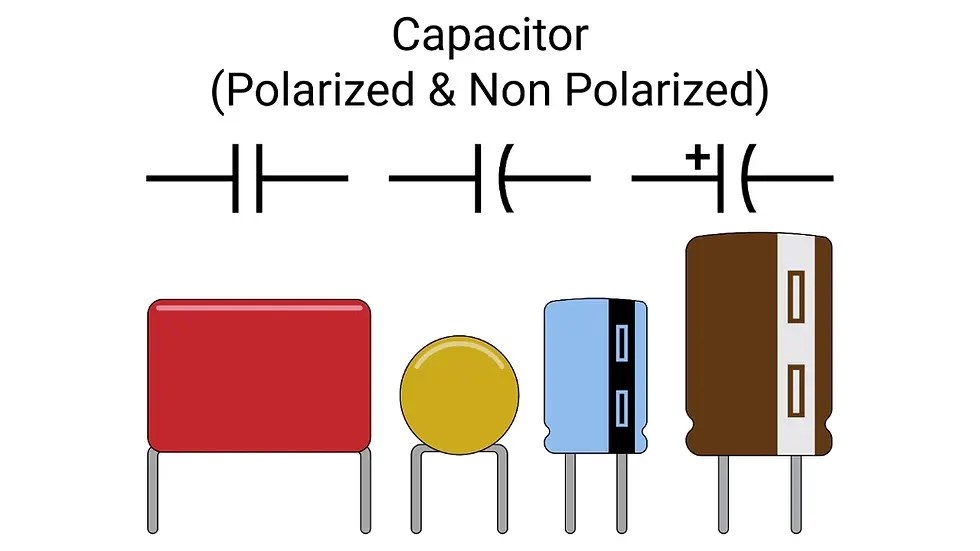
The basic capacitor symbol consists of two parallel lines separated by a small gap, representing the two plates of a capacitor. This symbol typically represents a non-polarised, fixed capacitor, which can be used in either direction within a circuit.
Symbol Meaning: A general-purpose capacitor with no polarity
Function: Stores and discharges electrical energy, filters unwanted signals, and smooths out voltage fluctuations
Application: Widely used in analog and digital designs for decoupling, signal conditioning, and timing circuits.
2. Fixed Capacitor Symbols
Fixed capacitors have a stable, unchanging capacitance value. In schematics, their symbols are often identical to the basic capacitor but may include annotations or sub-symbols to denote material or tolerance.
Symbol: Two parallel lines (non-polarised)
Function: Delivers stable and repeatable performance in signal timing, voltage regulation, and filtering.
Common Types:
Ceramic Capacitors – Compact and inexpensive; used for high-frequency applications
Film Capacitors – Known for its high reliability and precision
Tantalum Capacitors – Offer higher capacitance in a small form factor, but are polarised
Use Case: Frequently used in decoupling circuits, oscillator networks, and voltage smoothing across power rails
Polarized and Non Polarized Capacitor Symbols

In polarised capacitors, the orientation is critical. These electronic device components can only be installed one way due to their internal construction, making the symbol in the schematic vital to avoid reverse polarity errors during circuit board assembly.
Polar Capacitor Symbol: One straight line and one curved line (or a "+" sign on the positive terminal)
Non-polarised Symbol: Two equal-length straight lines
Function: Helps manage voltage flow, with polarized types suitable for DC power applications and non-polarized types for AC signal filtering
Use Case:
Polarized: Power supply filtering, energy storage
Non-polarized: Audio crossover networks, coupling/decoupling in signal paths
Variable and Trimmer Capacitor Symbols
Variable capacitors are represented with an arrow crossing the standard capacitor symbol, indicating that the capacitance value can be adjusted. These components are essential in circuits that require tuning or calibration.
Symbol: Capacitor icon with a diagonal arrow through or over it
Function: Enables manual adjustment of circuit frequency or timing by altering capacitance.
Use Case:
RF Circuits – For antenna tuning, signal matching
Oscillators – Fine-tuning frequency generation
Calibration Tasks – Adjusting filter response or signal timing\\
Types
Trimmer Capacitors
Small, board-mounted adjustable capacitors for infrequent calibration
Tuning Capacitors – Larger components are often used in radios or variable frequency oscillators
These components are especially useful during prototyping and product development, where frequency precision matters.
Electrolytic Capacitor Symbols
Electrolytic capacitors are known for their high capacitance values and compact design, making them indispensable in power supply and voltage filtering applications. Their schematic symbol always indicates polarity.
Symbol: A straight line (positive) and a curved line (negative)
Function: Stores energy, smooths out voltage changes, and supports power surge demands
Use Case:
Power Supplies – For voltage regulation and ripple filtering
Audio Circuits – For coupling and decoupling applications
Motor Controllers & Industrial Systems – Where large charge storage is required
Note: Reversed polarity during installation can cause the capacitor to fail or even rupture
During Printed Circuit Board assembly, clear identification of polarity markings in both the BOM and silkscreen layer is critical for quality assurance.
Interesting Reads: Thermal Profiling in PCB Assembly: The Key to Precision & Quality
Surface Mount and Leaded Capacitor Symbols
Though the capacitor symbol used in schematics remains mostly the same for both surface mount and through-hole types, the form factor significantly influences PCB manufacturing processes.
Surface Mount Capacitors (SMD)
Designed for high-density SMT PCB assembly
Offer compact size and compatibility with automated pick-and-place machines
Ideal for consumer electronics, mobile devices, and the compact industrial sectors.
Leaded Capacitors (THT):
Feature visible wire leads for through-hole insertion
Better mechanical stability in rugged environments
Often used in prototypes or low-volume, hand-soldered boards
Function: The choice between these types depends on design constraints, durability requirements, and production volume. OEMs often prefer SMDs for mass production, while THT capacitors remain useful for legacy systems or industrial-grade equipment.
Specialised Capacitor Symbols
Beyond the standard fixed, variable, and polarized capacitor symbols, there are several specialised capacitor symbols used in advanced or industry-specific circuit designs. These symbols provide greater clarity for engineers working on high-frequency, high-voltage, or safety-critical applications.
Understanding these symbols is particularly valuable for teams working in the medical industry, aerospace electronics, industrial automation systems, or communication hardware, where precise functionality and documentation are key to compliance and reliability.
Common Specialised Capacitor Symbols Include:
Safety Capacitors (Class X and Y)
Indicated with additional labelling or markings in schematics (e.g., “X1”, “Y2”)
Used in EMI suppression and line-to-ground protection
Typically appear in power supply input stages
Feedthrough Capacitors
May be represented with a special box-type symbol or a capacitor with ground indication
Designed to suppress high-frequency noise in signal lines
Common in RF, communication, and EMI-sensitive circuits
Snubber Capacitors
Marked alongside resistors in RC snubber configurations
Used to suppress voltage spikes in switching circuits (e.g., in motor control or relays).
High-Voltage Capacitors
Sometimes labelled with voltage-specific annotations (e.g., “HV”)
Utilised in power supplies, defibrillators, or industrial machinery
Important for preventing breakdown in high-energy environments
Temperature-Stable Capacitors
Marked by type (e.g., NP0, X7R) in addition to their symbol
Help maintain consistent performance across temperature variations
Commonly applied in automotive systems, aerospace electronics, and other high-reliability applications
Why They Matter in PCB Design?
Specialised capacitor symbols play a vital role during schematic review and component sourcing. Misinterpreting or overlooking them can lead to selecting inappropriate parts, resulting in circuit failure or non-compliance with safety standards.
Interesting Reads: Why is Surface Mount Technology Beneficial for PCB Assembly?
Different Standards for Capacitor Symbols
Capacitor symbols can vary depending on regional standards, industry requirements, or even company-specific documentation rules. For teams working with international clients, multi-site design teams, or global suppliers, recognising these variations is important for maintaining consistency and avoiding errors during design handoffs and production.
Here’s a breakdown of the most common symbol standards used in electronics:
1. IEC (International Electrotechnical Commission)
Widely adopted across Europe and Asia
Focuses on simplified and modern symbols
Non-polarized capacitors are shown with equal lines, while polarized ones have a "+" marker or curved line
Often preferred for automotive, industrial, and consumer electronics designs in global markets
2. ANSI (American National Standards Institute)
Commonly used in North America
May include more detailed representations (e.g., curved lines, specific lead placements)
Used in many defense, aerospace, and legacy system designs
Often appears in schematics from US-based OEMs and electronics contract manufacturers
3. Company-Specific or Custom Symbols
Internal design teams may develop custom variations for easier recognition or software compatibility
May include extra notations for voltage rating, tolerance, or safety class (e.g., X1/Y2 capacitors)
Found in proprietary CAD libraries and often aligned with internal documentation practices
Crucial to clarify with contract manufacturers like A2Z Electronics LLC during the onboarding process to ensure correct interpretation.
Conclusion
Capacitors are a core part of electronic design, and understanding how they are represented in circuit diagrams is key to building or repairing any device. From variable capacitor symbols that allow fine-tuning to the electrolytic symbol that shows polarity, each variation has a role in describing how energy is stored and controlled in your circuit.
At A2Z Electronics LLC, our team works with all different capacitor types and delivers reliable PCB assembly services built on clear, professional design. If you need support with your electronic components or help making sense of a schematic, we are ready to assist. Get in touch with A2Z to make your next project accurate, efficient, and fully supported.


