


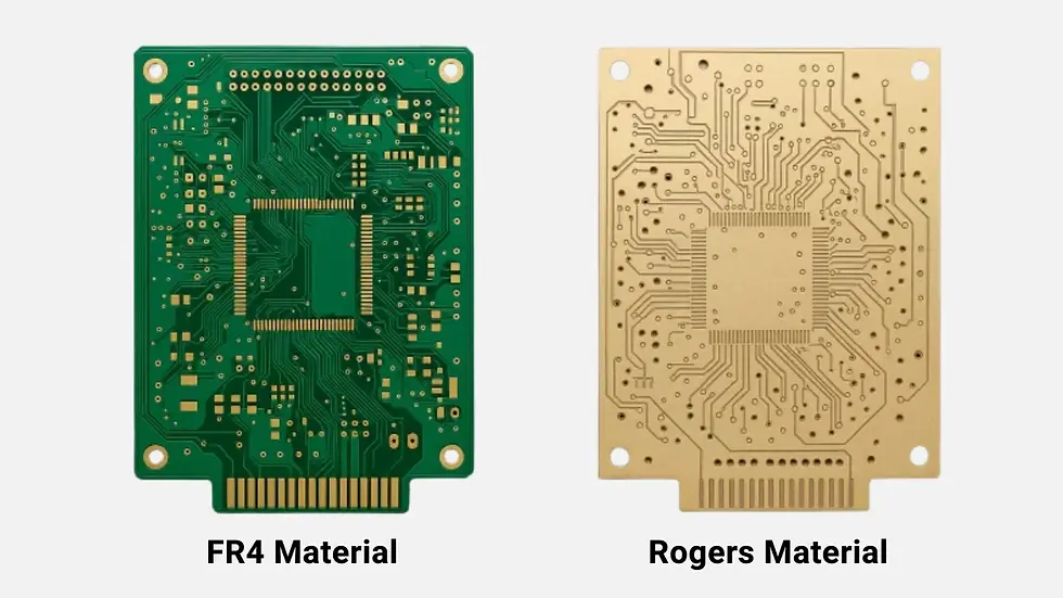
FR4 vs. Rogers: Which PCB Material Is Right for Your Project?
- Harshit Shah

- Mar 21
- 6 min read

Every PCB design begins with practical decisions that shape the final product. Material selection affects signal behavior, thermal performance, fabrication complexity, and overall project cost. One comparison that frequently comes up in engineering discussions is FR4 vs Rogers PCB.
At first glance, both are PCB substrate materials used to build reliable circuit boards. In real-world applications, they serve different performance levels and design goals. If you are developing consumer electronics products, FR4 may be sufficient. If your project involves RF signals or high-frequency communication, Rogers materials may offer advantages.
Let’s take a clear, experience-based look at FR4 vs Rogers PCB so you can align material choice with your actual design requirements.
Key Takeaways
FR4 PCB material is the industry standard for general-purpose electronics due to its affordability, mechanical strength, and broad availability.
Rogers PCB material is engineered for high-frequency and RF applications where low dielectric loss and stable electrical performance are required.
In a direct FR4 vs Rogers PCB comparison, the primary differences lie in dielectric constant stability, signal loss, thermal performance, and cost.
FR4 vs Rogers cost can vary significantly, with Rogers laminates typically costing multiple times more than standard FR4 materials.
FR4 is well-suited for consumer electronics, industrial controls, and standard digital circuits.
Rogers materials are commonly used in RF systems, 5G infrastructure, automotive radar, satellite communication, and microwave designs.
The decision in FR4 vs Rogers which is better depends on signal frequency, performance requirements, and budget constraints.
Table of Contents
What Is FR4 PCB Material?
FR4 is a glass-reinforced epoxy laminate. The “FR” stands for flame retardant. It is one of the most widely used PCB laminate materials in the electronics industry. Thanks to its balanced electrical insulation, mechanical strength, and affordability, FR4 has become the standard material for general-purpose boards.
Most everyday electronic products rely on FR4 PCB material, making it the default option in many designs.
Key Properties & Features of FR4

In any meaningful PCB material comparison, FR4 offers the following characteristics:
Dielectric constant (Dk) typically between 4.2 and 4.8
Higher dielectric loss compared to high-frequency PCB materials
Strong mechanical durability
Good insulation performance
Stable behavior in low- to mid-frequency applications
Cost-effective and widely available
FR4 performs well for digital circuits, power boards, and standard control systems. As frequency increases, signal loss becomes more noticeable.
Advantages of FR4 Material Over Rogers
When comparing FR4 material vs Rogers material, FR4 stands out in several areas.
Lower Cost
The difference in FR4 vs Rogers cost can be significant. FR4 is far more economical, especially in high-volume production.
Mature Manufacturing Process
Fabricators are deeply familiar with FR4. Processing, drilling, plating, and lamination are straightforward and predictable.
Broad Range of Applications
FR4 supports many common FR4 applications, including consumer electronics, industrial controls, and power management systems.
Strong Mechanical Structure
FR4 offers solid rigidity and durability, which benefits boards exposed to mechanical stress. If your circuit does not operate at high frequencies, FR4 often provides the right balance of performance and cost.
What Is Rogers PCB Material?
Rogers materials are engineered laminates designed for high-performance electrical behavior. They fall into the categories of high-frequency PCB materials and RF PCB materials.
Unlike standard epoxy-based laminates, Rogers PCB material is formulated to deliver stable dielectric properties and lower signal loss at elevated frequencies.
Key Properties & Features of Rogers PCB
In a direct FR4 vs Rogers comparison, Rogers shows strengths in these areas:
Low and tightly controlled dielectric constant
Very low dielectric loss
Excellent signal integrity at high frequencies
Strong thermal stability
Reliable performance across temperature variations
These properties make Rogers PCB material suitable for microwave circuits, millimeter-wave designs, and RF systems.
Advantages of Rogers Material Over FR4
Looking at Rogers material advantages over FR4, performance is the main difference.
Superior High-Frequency Performance
For RF and microwave circuits, Rogers reduces signal attenuation significantly.
Improved Signal Integrity
Lower dielectric loss means less energy dissipation and cleaner signal transmission.
Stable Electrical Properties
Consistent dielectric behavior supports controlled impedance designs.
Ideal for Precision RF Structures
Antenna designs and sensitive communication modules benefit from Rogers’ stability.
In projects requiring RF PCB materials or advanced high frequency PCB materials,
Rogers is often selected for performance reasons.
FR4 vs. Rogers PCB Material: 8 Main Differences & Comparison
The following table highlights the main differences between FR4 and Rogers PCB materials across performance, cost, and application areas.
Feature | FR4 Material | Rogers Material |
Dielectric Constant Stability | Less stable dielectric constant | More controlled and stable dielectric constant |
Dielectric Loss | Higher dielectric loss | Lower dielectric loss |
High-Frequency Performance | Suitable for low to moderate frequency circuits | Performs better in high-frequency applications |
Thermal Performance | Moderate thermal stability | Handles temperature variations more consistently |
Mechanical Strength | Strong structural durability | Good performance but generally less rigid than FR4 |
Processing Complexity | Easier to manufacture and widely supported | More complex manufacturing process |
Material Cost | Roughly $0.50 – $5 per PCB for common boards depending on size, layers, and volume | Roughly $10 – $50+ per PCB depending on RF grade material and manufacturing complexity |
Typical Applications | General electronics, consumer devices, industrial electronics | RF circuits, microwave systems, antennas, high-frequency communication equipment |
This PCB material comparison shows that each material fits a different performance range.
You May Also Read: Aluminum vs FR4 PCB: Key Differences and How to Pick the Right One
Cost vs Performance Analysis: FR4 vs Rogers
When evaluating FR4 vs Rogers cost, the difference is measurable in the U.S. market.
For standard production volumes in the U.S., FR4 laminate material typically ranges around $2 to $5 per square foot, depending on thickness and grade.
Rogers laminate materials commonly range from $20 to $60 per square foot, depending on the specific series and performance class. At the finished PCB level, a comparable Rogers board can cost 2 to 5 times more than an FR4 board, especially in multilayer or controlled impedance designs.
The multiplier depends on layer count, processing complexity, and material type. The price difference comes from Rogers’ engineered dielectric stability and low-loss performance.
If your design operates at low or moderate frequencies, FR4 often meets performance targets at a significantly lower cost. For RF modules, antennas, 5G systems, radar, or other high-frequency applications, Rogers materials reduce signal loss and improve consistency, which can justify the higher investment.
The practical approach is simple: align material performance with signal frequency. Using Rogers where FR4 is sufficient increases cost. Using FR4 where low-loss performance is required can lead to redesign and reliability issues.
Practical Assembly Considerations When Using FR4 or Rogers
Material choice also affects manufacturing and assembly.
Rogers materials may require tighter control during lamination and drilling
Hybrid stackups combining FR4 and Rogers require careful design planning
Differences in thermal expansion can influence long-term reliability
Understanding fabrication requirements early in the design stage helps avoid production challenges.
You May Also Read: PCB Fabrication vs. PCB Assembly: What are the Key Differences
Application Scenarios and Material Recommendations
Here is a practical look at FR4 applications and Rogers applications.
FR4 Applications
Power supplies
Standard digital circuits
Rogers Applications
RF communication equipment
5G infrastructure
Satellite communication
Microwave circuits
For general electronics, FR4 remains the dominant choice . For high-frequency and RF systems, Rogers fits better within the category of RF PCB materials.
FR4 vs. Rogers: Which Material Is Best for Your Project?
When asking FR4 vs Rogers which is better, the answer depends on your design goals.
Choose FR4 if your priority is cost efficiency and standard electrical performance. Choose Rogers if your design involves high frequencies, strict impedance control, and minimal signal loss.
There is no universal winner. The better material is the one that aligns with your signal requirements and production budget.

Conclusion
The discussion around FR4 vs Rogers PCB is about performance level and application focus. FR4 remains the industry standard for general electronics because of its affordability and reliability. Rogers provides enhanced electrical performance for high-frequency and RF designs.
A thoughtful material decision starts with understanding your circuit’s frequency range, signal integrity requirements, and cost targets. When those factors are clear, selecting between FR4 and Rogers becomes a straightforward engineering choice.


