Understanding Electrical and Electronic Symbols Used in Circuit Design
- Harshit Shah

- Aug 11, 2025
- 5 min read
Updated: Mar 25

Every electrical system starts with a schematic, and behind every schematic is a language of standardized symbols. These electrical electronics symbols represent core components like resistors, power sources, connectors, transistors, and integrated circuits. Instead of lengthy descriptions, circuit diagrams use these visuals to communicate complex electrical designs quickly and clearly.
For OEMs, product developers, and technical teams across industries such as aerospace, automotive, medical devices, and industrial automation, understanding these symbols is more than a skill—it’s part of the design, assembly, and troubleshooting workflow.
Whether your teams are prototyping a new control board or scaling up production, knowing these symbols helps convert engineering intent into working electronics with fewer delays and errors.
Table of Contents
What Are Electrical and Electronic Symbols?
Electrical and electronic symbols are standardized shapes used in circuit diagrams to visually represent components in a circuit. Instead of drawing the real part, designers use symbols to show how elements are connected and function within a system. They allow everyone—from design teams to repair technicians—to speak the same visual language.
You’ll find these symbols on blueprints, service manuals, PCB design software, and academic textbooks. Learning their meanings is like learning to read a map—it makes the whole system easier to understand.
10 Common Electrical Symbols and Their Meanings
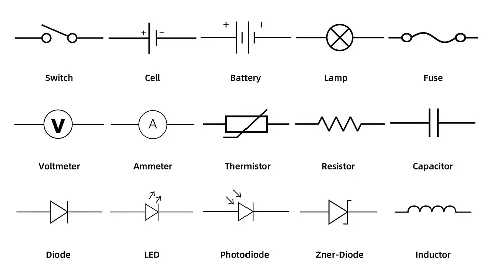
Understanding electrical symbols and meanings is key when reading or designing circuits that control or distribute electrical power. Below are ten common electrical symbols used in circuit diagrams, along with what they represent:
Resistor
Symbol: Zigzag line or rectangle
It is used to reduce current flow or divide voltage in a circuit. It's one of the most basic electrical components symbols and is found in nearly every schematic.
Battery
Symbol: A series of long and short parallel lines
A battery represents a power source with one or more cells. Essential for powering portable devices and part of many electric circuits symbols.
Ground (Earth)
Symbol: Three horizontal lines stacked vertically
Grounding provides a common return path for current. It helps stabilize voltage levels and protects components.
Interesting reads: What is GND in Circuits: Meaning, Types & its Importance
AC Voltage Source
Symbol: A circle with a sine wave inside
It is used in circuits that draw power from alternating current sources, such as household outlets.
DC Voltage Source
Symbol: Two parallel lines, one solid and one dashed
DC Voltage Source refers to direct current supplies like batteries or regulated power adapters.
Single-Pole Switch (SPST)
Symbol: A break in a line with a movable contact
SPST is used to open or close an electrical circuit manually—think of it as a basic on/off control.
Fuse
Symbol: A small rectangle with a line across
Fuse protects the circuit by breaking the connection if the current exceeds a safe level.
Lamp or Indicator Light
Symbol: A circle with a cross inside
An indicator light is used to indicate power status, faults, or operational states in a system.
Transformer
Symbol: Two coils separated by lines or a core
It transfers energy between two circuits, commonly found in power supplies and voltage adapters.
Capacitor (Non-Polarized)
Symbol: Two parallel lines with a gap
A capacitor stores electrical energy temporarily and helps smooth voltage fluctuations or provide timing delays. If want to Know more about capacitor symbols read our new blog on 6 Common Capacitor Symbols in Electronics You Should Know
These standard symbols for electronics simplify design and repair tasks, especially in power-heavy systems like lighting, HVAC, and industrial controls.
10 Common Electronic Symbols and Their Meanings
In digital and analog circuit designs, electronics symbols and meanings represent components that process signals or control circuit logic. Below are ten frequently used symbols and what they do:
Diode
Symbol: Triangle pointing at a line
Allows current to flow in one direction only, preventing reverse voltage damage. It plays a key role in managing power flow and safeguarding circuits.
LED (Light Emitting Diode)
Symbol: Diode with outward arrows
Emits light when powered. Found in displays, status indicators, and lighting applications.
Zener Diode
Symbol: Like a diode but with bent tips
Designed to allow current to flow in reverse when a certain voltage is reached, used for voltage regulation.
Transistor (NPN/PNP)
Symbol: Three terminals with arrows indicating current direction
Acts as a switch or amplifier. Core part of all modern electronics, from amplifiers to processors.
Integrated Circuit (IC)
Symbol: Rectangle with multiple connecting pins
Represents a packaged set of miniaturized electronic circuits. Used in everything from timers to microcontrollers.
Logic Gates (AND, OR, NOT)
Symbols: Unique shapes for each gate function
Used in digital circuits to perform operations like addition, comparison, and decision-making.
Operational Amplifier (Op-Amp)
Symbol: A triangle with two inputs and one output
Used to amplify weak electrical signals, found in audio devices, instrumentation, and control systems.
Crystal Oscillator
Symbol: A rectangle or overlapping lines with labels
Provides precise timing signals, critical in microcontrollers, clocks, and communication systems.
Photodiode
Symbol: Diode with arrows pointing toward it
Converts light into current, used in optical sensors and safety detection systems.
Potentiometer (Variable Resistor)
Symbol: A resistor with an arrow across it
Adjusts resistance in a circuit manually—used for volume controls, dimmers, and calibration circuits.
Each of these electronics parts symbols helps designers and engineers create schematics that are universally understood and technically accurate, improving both design quality and production efficiency.
Interesting reads: Top 10 PCB Components & Printed Circuit Board Parts in 2025
Applications of Electrical & Electronics Symbols
These symbols for electronics are used across sectors where accurate and reliable circuit documentation is critical:
Consumer Devices – Smartphones, TVs, and audio systems are all built from symbol-driven schematics.
Medical Electronics – Tools like ECG machines and infusion pumps require clean circuit layouts and electronics ground symbols .
Aerospace and Defense – Control panels, sensors, and navigation systems depend on detailed electric circuit symbols.
Automotive Systems – Everything from electric vehicles to infotainment runs on documented circuit diagrams.
Industrial Equipment – Robotics and control units rely on standard electronics parts symbols to streamline maintenance.
These symbols don’t just simplify design—they make repairs, audits, and upgrades more accurate and safe.

Interesting Reads: Top SMD Electronic Components for PCB Assembly Projects
Conclusion
Electrical and electronic symbols are more than design shortcuts they’re the language of innovation. Learning these electrical electronics symbols gives engineers and technicians the tools to design better systems, reduce errors, and stay in sync with industry standards. Whether you're reading a basic layout or planning a complex build, understanding these symbols helps keep your projects on track.
As an electronic manufacturing company in the USA, the teams at A2Z EMS, work with precise circuit schematics that use these standard symbols to deliver reliable, high-quality assemblies. From prototype to full-scale manufacturing, this shared visual language helps us translate complex ideas into working products that meet exact specifications. Get in touch to discuss your business needs.